domingo, 18 de outubro de 2015

terça-feira, 22 de setembro de 2015
Rugged computing terminology and standards
Rugged computing terminology and standards
(by Conrad H. Blickenstorfer)
(by Conrad H. Blickenstorfer)
What's
an IP rating? Ingress Protection? How is that measured, and what does
it mean? What does "intrinsically safe" mean? How do they do drop tests
and such? Where
can you find information on testing procedures? What are NEMA ratings?
What does RoHS mean, and is it important? (Yes, especially if you deal
with European markets). And what's FIPS 201? Or does a client request
adherence to IEC 60601? Or what does a vendor
need to do to comply with MIL-L-85762A for night vision imaging systems?
All
of these terms, and more, you'll encounter in this specifications and
sales pitches of rugged computing equipment. Knowledge of what it all
means is crucial to understanding
the potential suitability of equipment for your applications, and also
when discussing your needs with a vendor.
In
this section you'll find explanations of the many definitions and terms
used in rugged computing, and also information on the various rating
systems employed to indicate
ruggedness, sealing and other environmental protection. You'll also find
descriptions and updates on enabling technologies, such as
outdoor-readable notebook computers screens.
You
also find primers of a variety of ancillary technologies, such as RFID,
bar code scanning, and others. What you see now is just the beginning.
Over time we'll be
adding additional definitions, primers, and white papers.
Vendors: If you have Technology White Papers which you'd like to share with potential clients, please email us at cb@pencomputing.com.
At
RuggedPCReview.com we consider the Ingress Protection rating to be
especially important. It is in the IEC (International Electro technical
Commission) 60529 international
standard and classifies how well electrical enclosures are protected
against intrusion of solid objects, dust, and water. When used to
indicate sealing of rugged computers, the IP rating tells you whether
dust or water can get into your computer. Below is the
IP rating table.
IP (Ingress Protection) Rating Table
| SOLIDS (1st number) | LIQUIDS (2nd number) | ||
| 0 | No protection | 0 | No protection |
| 1 | Protected against objects > 50mm (hands) | 1 | Protection against dripping water or condensation |
| 2 | Protected against objects > 12mm (fingers) | 2 | Protection against water spray 15 degree from vertical |
| 3 | Protected against objects > 2.5mm (tools/wires) | 3 | Protection against water spray 60 degree from vertical |
| 4 | Protected against objects > 1mm (small tools) | 4 | Protection against water spray from all directions |
| 5 | Protected against dust, limited ingress | 5 | Protection against low pressure jets of water |
| 6 | Totally protected against dust | 6 | Protected against heavy seas |
| 7 | N/A | 7 | Protection against the effects of immersion (6 inches to 3.3 feet) |
| 8 | N/A | 8 | Protected against continuous immersion (but under conditions defined by the manufacturer) |
What is the MIL-STD-810F
It
is an equipment testing standard by the United States Department of
defense. It describes in detail testing procedures designed to determine
how equipment holds up
under a variety of conditions the equipment may encounter while being
used, transported and stored. These conditions include temperature,
impact, vibration, humidity, and more. Note that while the standard is
extensively used for testing of rugged computing
equipment, it was not specifically designed for that type of equipment.
As a result, some tests are ambiguous when applied to computing
equipment.
What is the difference between MIL-STD-810F and MIL-STD-810G?
MIL-STD-810F
was introduced on January 1, 2000. MIL-STD-810G was introduced October
31, 2008, and supersedes MIL-STD-810F. The two documents are not
substantially different,
but different enough so that many testing procedures have different
articles and numbers. As of late 2011, most rugged manufacturers have
switched to providing ruggedness testing information using MIL-STD-810G,
but some still cite the older standard.
What's MIL-STD-810F Method 506.4 (Rain)?
Manufacturers
often refer to MIL-STD-810F Method 506.4. The MIL-STD-810F is a
Department of Defense document that describes test methods for
environmental engineering
considerations and lab tests in great detail (Note that MIL-STD-810G,
issued October, 2008, has superseded MIL-STD-810F). Method 506.4
describes testing to determine how well a piece of equipment is
protected from rain, water spray, and dripping water.
Procedure I tests resistance to rain and blowing rain, with variations up to 45 degrees from the horizontal.
Procedure II sprays all exposed surfaces with water for not less than 40 minutes per face.
Procedure III drips water from no less than 3 feet for 15 minutes.
What's MIL-STD-810F Method 509.4 (Salt Fog)?
Salt
fog can quickly ruin equipment. 509.4 describes testing methods to
determine the effectiveness of protective coatings and finishes on
materials for corrosion, electrical
effect and physical effects. It can also determine the effects of salt
deposits on the physical and electrical aspects of materiel. The product
is exposed to salt fog mist from a 5% salt solution via atomizers at
about 95 degrees Fahrenheit for a minimum of
four alternating 24-hour periods, two wet and two dry. The product is
then examined for salt deposits that can clog or bind components,
electrical malfunction, and potential short and long-term impact of any
observed corrosion.
What's Intrinsic Safety?
Intrinsic
safety is a requirement that may be applicable to devices that are
being operated in areas with flammable gases or fuels. It means that the
device is incapable
of igniting those gases. In short, an intrinsically safe piece of
equipment won't ignite flammable gases, See our Intrinsic Safety page, and for more detail
ecom instruments' intrinsic safety section.
What's MIL-STD-810F Method 510.4 (Sand and Dust)?
Specs
also often include references to MIL-STD 510.4. Those are tests that
evaluate the ability to resist the effects of dust that may obstruct
openings, penetrate cracks,
crevices, bearings, and joints and to evaluate the effectiveness of
filters.
Procedure I tests if the device can keep out blowing dust.
Procedure II determines if it is sealed against blowing sand.
Procedure III tests what happens if dust settles on the computer as that can affect heat dissipation or clog up filters.
What's MIL-STD-810F Method 516.5 (Drop)?
MIL-STD-810F
516.5 also often appears in ruggedness specs. This tests a device's
ability to survive a variety of impacts and shocks. MIL-STD-810F Method
516.5 defines
the purpose of the shock test to "provide a degree of confidence that
materiel can physically and functionally withstand the relatively
infrequent, non-repetitive shocks encountered in handling,
transportation, and service environments."
Procedure
IV -- Transit Drop -- is especially popular with rugged computing
equipment vendors and commonly called "drop test" or "drop spec." The
test requires that
items weighing 100 pounds or less survive a total of 26 drops on each
face, edge and corner. The 26 drops can be divided among up to five
samples of the same test item, which probably means used the first until
it fails, then start with the second, and so on,
although the language is not clear. Drop distance generally depends on
"how materiel in the field might commonly be dropped." Table 516.5-VI
(Transit Drop Test) shows that items weighing less than 100 pounds with a
largest dimensions of less than 36 inches,
i.e. virtually all mobile computers, must be dropped from 48 inches
because "a light item might be carried by one man, chest high; thus it
could drop 122 cm (48 inches). It also appears that the test is
conducted with the equipment off.
While most manufacturers test using Procedure IV (Transit Drop), testing according to other procedures might make more sense:
- Procedure I (functional shock) test is designed to "test materiel (including mechanical, electrical, hydraulic, and electronic) in its functional mode and to assess the physical integrity, continuity and functionality of the materiel to shock." It also says that the intent of Procedure I is to disclose equipment malfunction that may result from shocks experienced by materiel during use in the field. Eben though materiel has successfully withstood even more severe shocks during shipping or transit shock tests, there are differences in support and attachment methods and in functional checking requirements that make this test necessary. A shock apparatus is used and equipment must remain functional with a sawtooth pulse of at least 40G for 11ms (truck/vehicle-mounted 20G).
- Procedure III (fragility) is designed "to determine the maximum level of input to which the materiel can be exposed and still continue to function...". In Procedure III, drop height is defined as "the height from which the materiel might be dropped in its shipping configuration and be expected to survive." "Suggested drop height" for items up to 20 pounds is 30 inches.
Realize
that all these MIL-STD-810F 516.5 procedure were really designed to
measure the effectiveness of packaging, so applying this to dropping
actual devices is a
bit of a reach. And simply stating that a device is "tested according to
MIL-STD-810F" by itself means nothing. Detailed explanation as to what
was tested and what the outcome was must be included, and as a minimum,
Procedures I and IV should have been done
and passed.
Note
that according to the DOD, field data suggests that a typical piece of
equipment will be dropped from heights up to four feet an average of
four to six times during
its life cycle.
What other MIL-STD-810F tests are there?
The
MIL-STD-810F is a very comprehensive document. As a result, a statement
saying a device is "MIL-STD-810F tested" doesn't provide enough
information. The MIL-STD-810F
is an almost 600 page document with tests for about two dozen things
that can affect a piece of equipment. The tests are:
- 500.4 Low Pressure (Altitude)
- 501.4 High Temperature
- 502.4 Low Temperature
- 503.4 Temperature Shock
- 504 Contamination by Fluids
- 505.4 Solar Radiation (Sunshine)
- 506.4 Rain
- 507.4 Humidity
- 508.5 Fungus
- 509.4 Salt Fog
- 510.4 Sand and Dust
- 511.4 Explosive Atmosphere
- 512.4 Immersion
- 513.5 Acceleration
- 514.5 Vibration
- 515.5 Acoustic Noise
- 516.5 Shock
- 517 Pyroshock
- 518 Acidic Atmosphere
- 519.5 Gunfire Vibration
- 520.2 Temperature, Humidity, Vibration, and Altitude
- 521.2 Icing/Freezing Rain
- 522 Ballistic Shock
- 523.2 Vibro-Acoustic/Temperature
Each test has various
procedures and methods, and each may or may not be relevant to a
particular application. Major rugged equipment manufacturers have their
own testing labs where they can conduct MIL-STD-810F
testing. This is generally done in conjunction with testing in an
independent lab.
What is the MIL-STD-3009?
MIL-STD-3009
(also referenced as DOD-STD-3009) is another standard manufacturers of
rugged equipment may refer to. It sets requirements for aircraft display
equipment for use with night vision imaging systems. For mobile
computers that generally means they must not interfere
with night vision equipment in a cockpit.
Part
of this document is the U.S. Navy MIL-HDBK-87213 Revision A
(Electronically/Optically Generated Airborne Displays) that describes,
among other, criteria for legibility
of electro-optical display equipment and daylight readability in bright
environments, which is a military requirement. This can be an issue with
daylight readable displays marketed to the government and armed forces.
What is ASTM 4169?
At
times, rugged product descriptions refer to ASTM 4169, Truck Transport,
11.5.2 Random test, Assurance Level 2. ASTM stands for American Society
for Testing and Materials
and the 4169 standard sets tests and requirements for strength,
durability and protective capability of packaging. Level II stands for
medium test intensities (Level I is highest and Level II lowest) and is
most commonly used.
What is the MIL-STD-461E?
MIL-STD-461E
establishes interface and associated verification requirements for the
control of the electromagnetic interference (emission and
susceptibility) characteristics of electronic, electrical, and
electromechanical equipment and subsystems designed or procured for
use by activities and agencies of the Department of Defense. The
standard primarily applies to electronic enclosures no larger than an
equipment rack, electrical interconnections between enclosures, and
electrical power input
from prime power sources.
What is UL 1604?
You may come across references to UL 1604. This is not a governmental or industry association standard, but a certification by Underwriters
Laboratories Inc. UL is an independent product safety
certification organization that has been testing products and writing
standards for product safety for over a century. They have over 60
testing labs and have developed over 1000 standards.
UL 1604 is a certification document
and covers equipment, circuits, or components intended for use in
hazardous locations. This basically deals with a unit's safeguarding
against causing ignition of specified flammable gas- or vapor-air
mixtures.
What does "embedded" mean?
There
are various definitions. "Embedded" is often used for products or
projects where the computer is just part of a larger system, and not a
standalone PC. Intel uses
the term differently. For them, "Embedded indicates that Intel
anticipates shipping the product for an extended period of time.
Embedded parts typically need to be procurable for 7+ years, whereas
standard parts are typically procurable for 2+ years."
What is "PCI compliance"?
In
the payment processing industry, PCI stands for "Payment Card
Industry." The PCI has the "Payment Card Industry Data Security
Standard" (PCI DSS), which is a set
of requirements designed to ensure that all companies that process,
store or transmit credit card information maintain a secure environment.
PCI also issued the Payment Card Industry Security Standards Council
(PCI SSC) to cover the ongoing evolution of the
transaction process. See the PCI Compliance Guide here.
Why is altitude testing important?
Testing
procedures designed to ascertain the ability of a piece of equipment to
operate at high altitude are described in MIL-STD-810G Method 500.5
2.3.1 b(1). However,
that test arbitrarily uses 15,000 feet, which is more than the 7,000
feet atmospheric pressure in a commercial airplane, but a good 2,000
feet less than even Mt. Everest's base camp. Why does it matter whether a
piece of rugged computing equipment can operate
in high altitude? Because at 19,000 feet, air pressure drops to half
from what it is at sea level, meaning there are half the air molecules
available for cooling and any other operation that requires air pressure
for normal functioning.
What is the difference between OEM and ODM?
OEM
stands for Original Equipment Manufacturer and describes a company that
designs products according to their own specifications, builds them,
but the products are
then sold by another company under that company's name or brand.
ODM
stands Original Design Manufacturer and describes a company that builds
a product based on another company's design and specifications.
terça-feira, 25 de agosto de 2015
BGA Solder Ball Shelf Life
August 24, 2015
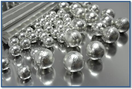
I believe BGA Solder Balls are a homogeneous mass of metals, why is the shelf life only two years? With proper handling and storage, can the shelf life be extended?
V.P.
I believe BGA Solder Balls are a homogeneous mass of metals, why is the shelf life only two years? With proper handling and storage, can the shelf life be extended?
V.P.
| Experts Comments |
| The solder alloy itself should not change composition significantly
over a period of several years. The main potential issue is oxidation of
the surface of the BGA solder ball. Even when stored properly air will
eventually make its way to the solder surface
and oxidation will occur. As the oxide layer grows the balls will become more difficult to solder. The rate of oxidation is slow enough that the balls will be usable for at least two years, but may be difficult to use after that time. |
|
|
Tony Lentz
Field Applications FCT Assembly Mr. Lentz has worked for FCT Companies for 14 years as a Lab Manager and Facility Manager. Over the last 2 years he has worked in Field Application for FCT Assembly. He holds BS and MBS degrees in Chemistry. |
|
| The shelf life, as defined by the manufacturer, takes into account
all aspects of the package, but let's stick to the solder ball
characteristics. You are correct that the balls are a homogeneous alloy.
So what might degrade after two years? Assuming that the parts are stored in MBBs compliant to J-STD-033, moisture will not play a role; the MBB and desiccant will protect against moisture ingress for approximately three years. The MBB does not, however, protect against oxygen, and the surface of the balls will oxidize over time. It is very likely that, after two years properly stored, solderability will be quite acceptable. It's just not guaranteed. Can we extend this time? The answer is, certainly we can, if we exclude oxygen. For long-term storage of parts for aerospace applications, where a program needs to be supported for a decade or more, we use nitrogen inerted cabinets, which both exclude oxygen and moisture. This eliminates surface degradation of parts. It does not, however, eliminate growth of intermetallic compounds, which will occur over time. IMC growth only impacts solderability when it grows through to the surface, however, which is something you won't see on BGAs. Bear in mind that any steps you take to extend solderability still don't affect the warranted period for solderability, only the practical life. |
|
|
Fritz Byle
Process Engineer Astronautics Fritz's career in electronics manufacturing has included diverse engineering roles including PWB fabrication, thick film print & fire, SMT and wave/selective solder process engineering, and electronics materials development and marketing. Fritz's educational background is in mechanical engineering with an emphasis on materials science. Design of Experiments (DoE) techniques have been an area of independent study. Fritz has published over a dozen papers at various industry conferences. |
|
| Unfortunately solder suppliers have no control how their products
are handled once they leave the factory. Also, the products are shipped
to a wide variety of locations and climates including humid areas as
well as locations near salt water. With this knowledge,
the solder has to protect against returns involving old and oxidized
product. For this reason these forms of solder are assigned a shelf life. With that said, the assigned shelf life is often conservative, and the product, if stored and handled properly and used with a flux, are usable well beyond the stated shelf life. I often encourage the end user to establish an internal protocol to recertify or lengthen the shelf life of the product. This would typically involve simple wetting tests with fluxes and substrates representative of what is used in their actual products. Some solder suppliers offer testing to "recertify" the product. However, the fee for so doing, is often near or close to the cost of just buying new product. |
|
|
Eric Bastow
Senior Technical Support Engineer Indium Corporation Eric is an SMTA-certified process engineer (CSMTPE) and has earned his Six Sigma Green Belt from the Thayer School of Engineering at Dartmouth College. He is also a certified IPC-A-600 and 610D Specialist. He has an associate's degree in Engineering Science from the State University of New York and has authored several technical papers and articles. |
|
| Many BGA manufacturers have a standard 2-year shelf life for their
products. I have also seen others which recommend just one year. Proper
handling and storage may extend the life of the BGA but it is not a
predictor of its performance and reliability.
One way of predicting shelf life would be to expose the components to some type of accelerated aging process to see if there is a change in component's physical properties along with its performance within the circuit. |
|
|
|
| Edithel Marietti Senior Manufacturing Engineer iDirect Edithel is a chemical engineer with 20 year experience in manufacturing & process development for electronic contract manufacturers in US as well as some major OEM's. Involved in SMT, Reflow, Wave and other assembly operations entailing conformal coating and robotics. |
sábado, 8 de agosto de 2015
terça-feira, 28 de julho de 2015
Accelerometer Mounting Accessories
|
segunda-feira, 27 de julho de 2015
quarta-feira, 22 de julho de 2015
Excess Flux Residue After Hand Soldering
July 10, 2015
|
|
We observe an excessive amount of flux after hand soldering terminals using flux cored wire solder. See the image.
Is this amount of excess flux normal?
Is there something wrong with our manual soldering operation?
K.K.
Is this amount of excess flux normal?
Is there something wrong with our manual soldering operation?
K.K.
|
Experts Comments
|
|
The answer is it depends
but this appears to be excessive on the contact, but was a different
amount of solder wire or larger core used to solder the sample. I would
be more concerned is the flux
benign or still corrosive (no clean flux requires additional heat to
complex the flux to create a benign residue and this looks like it is
far from the solder joint heating).
The other question to ask if this is insulative do you want it on the contact that is designed to make electrical contact. |
|
Terry Munson
President/Senior Technical Consultant Foresite Mr. Munson, President and Founder of Foresite, has extensive electronics industry experience applying Ion Chromatography analytical techniques to a wide spectrum of manufacturing applications. |
|
|
The picture shows flux
residue from soldering using solder wire which is not uncommon. Flux
residue will depend on the percentage of flux in the wire. Flux percent
by weight will vary from 0.5% to
3% in solder wires and higher percentages will leave more visible flux
residue.
Less flux in the wire, less flux residues, however you need a good percentage to enable ease of soldering. Usually 1, 2 or 3 % flux is best with 0.5% being more difficult to use by operators. If the residue is from flux that are no-clean in nature the residue will not cause issues normally. Most no-clean solder wires are described as ROL0. No-clean, RA, RMA flux wires have fluxes which are resin based and slightly higher or lower soldering tip temperatures will not impact the volume of visible flux. Resins tend to have high boiling points and do not vaporize with soldering tip temperatures. If temps are too high the resin will darken and burn. This will render it harder to clean off later. |
|
Peter Biocca
Senior Market Development Engineer Kester Mr. Biocca is a chemist with 24 years experience in soldering technologies. He has presented around the world in matters relating to process optimization and assembly. He has been working with lead-free for over 8 years. He is the author of many technical papers delivered globally. |
|
|
Flux residue is
proportional to the percentage of flux in the wire and the amount of
wire fed into the joint. Wire solder that is '2% flux core' is 2% flux
core by weight - it's approximately 50%
by volume.
Therefore, if the joint accepts a lot of solder, then there is going to be more residue. In the image you provided, the terminal looks to hold a lot of solder therefore you could expect more visible residue, but I would not consider it excessive. You could experiment with different manufacturers wire solder products to see if they leave less residue as flux formulation can significantly impact location/appearance/volume of residue. |
|
Tim O'Neill
Technical Marketing Manager AIM Tim O'Neill is the Technical Marketing Manager for AIM Products. AIM is a global supplier of materials for the PCB assembly industry including solders, fluxes and thermal management materials. Tim has a B.A. from Assumption College and post-graduate studies in education. He has 20 years of experience in the electronics soldering industry, beginning his career in 1994 with EFD and was key in business development of their fine pitch solder paste dispensing technology. Tim joined AIM in 1997 and has since assisted many clients with assembly challenges, specializing in Pb-Free process development and material selection. |
|
|
First, it is assumed that
this is a No-Clean flux-cored solder wire. If not, then the residue
would have to be removed. If this is a No-Clean flux-cored solder wire
there is nothing wrong with your
soldering but ways to make it look better.
Seeing that the flux-cored solder wire has been heated fully to alloy melting, the flux within has been heated sufficiently to
The amount of residue can
be controlled somewhat by adjusting the diameter of the flux-cored
solder wire. Try using a smaller diameter for less flux residue; the
smallest diameter that will do the
job.
The IPC-610 standard for workmanship allows flux residue resulting from hand-or machine-soldering as long as the residue has been heated sufficiently to activate it. Any surface that has achieved soldering temperature will certainly render the flux residue activated. |
|
Gary Freedman
President Colab Engineering A thirty year veteran of electronics assembly with major OEMs including Digital Equipment Corp., Compaq and Hewlett-Packard. President of Colab Engineering, LLC; a consulting agency specializing in electronics manufacturing, root-cause analysis and manufacturing improvement. Holder of six U.S. process patents. Authored several sections and chapters on circuit assembly for industry handbooks. Wrote a treatise on laser soldering for Laser Institute of America's LIA Handbook of Laser Materials Processing. Diverse background includes significant stints and contributions in electrochemistry, photovoltaics, silicon crystal growth and laser processing prior to entering the world of PCAs. Member of SMTA. Member of the Technical Journal Committee of the Surface Mount Technology Association. |
|
|
The amount of flux does
not seem excessive. Soldering this type of terminal requires a fairly
high volume of solder, so there will be more residue than for a smaller
joint. It may be possible to reduce
the amount of residue by purchasing solder wire with a lower flux
percentage.
Speak with your solder manufacturer about what you are now purchasing, and whether a version with lower flux percentage is offered. If it is, you will need to test it to see whether the reduced flux activity due to less flux is adequate for the application. One other thought; if the flux running down the terminal is of concern, re-orienting the terminal during soldering may avoid this, but of course the residue will still be present. |
|
Fritz Byle
Process Engineer Astronautics Fritz's career in electronics manufacturing has included diverse engineering roles including PWB fabrication, thick film print & fire, SMT and wave/selective solder process engineering, and electronics materials development and marketing. Fritz's educational background is in mechanical engineering with an emphasis on materials science. Design of Experiments (DoE) techniques have been an area of independent study. Fritz has published over a dozen papers at various industry conferences. |
|
|
From the photo is appears
that your operator is adding flux prior to hand soldering. The flux is
too far away from the solder joint so I would check this first. If this
is not the case, from the photo
it appears that the flux is not activated (as shown) which could mean:
|
|
Gary Goldberg
President and CEO PROMATION, Inc. Mr Goldberg has practical experience in production line layout, process flow and cycle rate analysis. He knows how to avoid bottle necks and most related PCB or pallet handling questions. |
|
|
To determine if the
electrical performance will be compromised, a surface insulation
resistance test (available in the IPC Test Methods) will show if the
residue will be sufficient enough to compromise
the finished PCB. Hand soldering temperatures can vary significantly.
Soldering tip in relation to board density (which can act as a heat sink) , not to mention the human factor, can add up to inconsistent heating ultimately leading to excessive residue. |
|
Stephanie Nash
Director Integrated Ideas & Technologies, Inc. Stephanie Nash is the Director of Technical Services & Marketing for Integrated Ideas & Technologies, Inc., a premier manufacturer of SMT stencils. She has been instrumental in the stencil design and technical support. |
Solder Joint Opens - What To Do?
Electronic
components are soldered to circuit boards every day and in some cases
opens are found during x-ray inspection or during
the test. You may be inclined to re-heat and reflow the solder using a
little extra flux. It's reasonable to think this will work but it can be
deflating when it is not effective.
In a desperate attempt to correct the defect, the process may be repeated at higher temperatures or for a longer cycle. Yet again, the opens may remain.
While attempts at secondary reflow may often work successfully, it will not work when there are pads with high levels of oxidation. The only way to reliably rework this type of defective solder joint is to remove the component, condition the pads by removing the oxidation followed by tinning, and finally reinstalling the component.
In a desperate attempt to correct the defect, the process may be repeated at higher temperatures or for a longer cycle. Yet again, the opens may remain.
While attempts at secondary reflow may often work successfully, it will not work when there are pads with high levels of oxidation. The only way to reliably rework this type of defective solder joint is to remove the component, condition the pads by removing the oxidation followed by tinning, and finally reinstalling the component.
|
|
|
Partially wetted pads.
|
Multiple
heat cycles not only overheat the components, but also overheat the
pads and soldermask, especially when higher lead-free
solder temperatures are required. Adjacent components and solder joints
can also be impacted negatively.
Damage to component packaging, fractured solder joints, and base board discoloration are some common side effects. It is a perplexing situation. Ask anyone who has pressed down on a component with an open to see it function properly but then when the pressure is removed, the open returns.
The best practice after the first attempt at secondary reflow is to either remove the component and investigate the situation or send the circuit board to a specialist for rework.
Damage to component packaging, fractured solder joints, and base board discoloration are some common side effects. It is a perplexing situation. Ask anyone who has pressed down on a component with an open to see it function properly but then when the pressure is removed, the open returns.
The best practice after the first attempt at secondary reflow is to either remove the component and investigate the situation or send the circuit board to a specialist for rework.
Several members of the Circuit Technology Center team contributed to this feature story.
Assinar:
Postagens (Atom)